


Builds & Racing
WIRC SBX-2 build – how I built my first WIRC 1/8 chassis
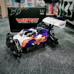
As promised, here’s a brief account of how I built myself a new WIRC SBX-2 nitro buggy for the 2024 summer off-road season. The backstory of discovering WIRC is in the previous blog post, which I definitely recommend reading, preferably before you start on this one.
ClayPitRC received the first three chassis in mid-March – a 1/8 scale electric (SBXE-3) and nitro buggy (SBX-2) and an electric truggy (RTXE-1). All of them already had owners waiting to get their hands on them and get the cars running. The nitro buggy was left for me. The goal was to get to know all three and get at least one chassis running in each official class.
First impressions and packaging
By the time I finally found the time to even open the box, the other cars were already half built, and I was a couple of days behind with mine. Since I wanted to film the whole build process to make a step-by-step video series later, the build needed a bit of planning and timing. One fine day I thought I’d just peek into the box and see what’s inside and how the quality of the parts looks. Actually, I already had some preview of the quality, as a small amount of basic spare parts had arrived together with the cars.
The box is open, and quite quickly I notice that one familiar item is missing – a printed paper build manual. I ask the owners of the other two cars whether theirs is missing too, as at first I think it may have been left out by accident. It turns out none of the kits came with a printed manual. However, I find a printed info sheet in the box saying that the manual can be downloaded digitally from wircracing.com. Actually, that makes sense. At most, you’d use the manual for the initial build, and after that the paper disappears somewhere at the bottom of a drawer and is forgotten. It saves a bit of nature too, and in digital form the manual is always up to date.
With the manual sorted, I look further. The parts in the kit are packed into 20 logical build stages. In addition, the box contains the chassis plate, an unpainted body and a bag with the rear wing hardware, which hasn’t been given a number. In that sense, a fairly standard packing solution. And indeed, everything you need for a given stage is in the corresponding bag. From previous experience with other manufacturers, I can say that sometimes certain parts needed for a stage have been in another bag and you can’t find them at first. So the packing gets a solid 5+.
Differentials (bags 1-3)
The build starts with the differentials – parts bags no. 1, 2 and 3. There are 3 diffs, as usual on this type of model. The kit includes one 5000 cst oil for filling all the diffs. The centre diff goes together first, and on this car it uses a different diff case from the front and rear ones – namely, it’s slightly longer. The general construction of the diff is completely standard and comparable to other manufacturers. What does stand out are the large washers that go inside the diff case between the outdrive and the retaining pin. AE cars, for example, don’t have these washers at all, which is extremely odd, but on the WIRC car these washers are especially chunky – maybe even around 1 mm thick. Another observation from the centre diff build is the gasket that goes between the case and the spur, which fits extremely precisely. At first I even wonder whether the gasket’s diameter might be slightly too large, but it turns out it just has a very tight tolerance and everything fits together perfectly. The other 2 diffs go together just as nicely, and I won’t dwell on them further. All three diffs are separate stages, so the build continues with bag no. 4.
As a side note – the manual shows where grease or thread lock should be added during the build. These materials are not included in the kit, and you’ll need to find them in your own supplies or buy them separately. In the places marked “grease”, I used black graphite grease.
Diff cases (bags 4-5)
Bags 4 and 5 are the rear and front diff cases with everything that goes with them: centre driveshafts, diff pinion, rear shock tower, body post, screws and bearings. Everything fits together nicely again. Design-wise, the diff case is such that the diff can be removed quickly and easily by removing four screws. At this stage I briefly catch myself thinking that something is wrong. I’ve just put the diff into the case and pressed the case cover on with my finger. The diff wobbles in the case as if the bearings were missing. I peek inside the diff case, but the bearings are there. The confusion continues. I then decide that before admitting there’s a problem, I’ll screw the cover on anyway and see what happens. Tightening the screws helps and the problem disappears. The same thing happens with the front diff case, so it seems everything is correct and the finished assembly works as it should.
Front suspension (bags 6-8)
Bag 6 Front arms, hinge pin holders, shimming. WIRC models have so-called “pivot ball” front suspension – just as a side note. The hinge pin holders are nice black aluminium, and as usual, replaceable plastic inserts are used to adjust the arm angles. Here I have to nitpick a little about these inserts. Firstly, you can see that the mould used to make them could be of better quality. Secondly, they only go into the aluminium with a lot of force, i.e. extremely tightly. On the one hand, of course, they’re then firmly in place, but replacing them can be moderately complicated, especially when the holders are on the car. There’s also a small plastic tree with shims of different thicknesses, to be used in the required amount to adjust the arm play. Everything goes together nicely.
In the next stage (bag 7), you add the front anti-roll bar, the upper arms with the so-called top plate and the shock tower. C-clips are used to move the upper arms forward and back. For me, the movement got a little stuck when I used all of these clips. There could be two reasons for this. Maybe I didn’t press the hinge pin insert 100% into the aluminium socket, or the clips together are just a bit too thick. One option would be to sand a clip a little thinner, sand the arm a little narrower, or just hope that everything wears in by itself during the first run. In general, with a new kit it’s more the rule than the exception that some spots are a bit tight and need running in.
Bag 8 contains the front steering knuckles, i.e. you need to assemble the main components of the pivot ball suspension together with the driveshafts. Again, there’s nothing revolutionary here and everything is standard. The steering link mounts are separate carbon fibre parts that are screwed onto the knuckle. What may be different from others is that WIRC includes 2 steel ball joints and 2 aluminium ones in the kit. Aluminium is usually optional, and with other manufacturers you have to buy them separately if you want them. The idea of the aluminium ones is that they go on top and, being lighter than steel, reduce the mass located up high. On the steering block, the plastic is threaded to make it easier to install the cap that holds the ball joint ball in place. The lower cap goes in easily. Maybe even too easily – hopefully the cap won’t start unscrewing itself. The upper cap, however, needs so much force to screw in that a regular hand screwdriver isn’t enough. I even start to think that maybe it’s not the thread and I’m screwing the cap into the socket at an angle or simply missing the thread. But when I unscrew it again, there’s no damage to the plastic thread, so I can assume the part is just so tight that it really does need more force. So I dig out the long handle from a socket set to make use of the lever effect known from physics to apply more torque, and I get the caps nicely screwed in. All that’s left is to screw the knuckles onto the ends of the arms, and the front axle is essentially done.
Rear suspension (bags 9-11)
Bag 9 contains the rear arms and holders, where everything is done similarly to the front, but of course there are no big balls here. Everything again fits together perfectly after I discover that to adjust the wheelbase you don’t use the spacers attached to the arms, but the ones on a separate small tree. Unfortunately, I had already removed some material from the arms to get them moving more freely. Of course, I thought I’d discovered a problem with the fit of the parts, but it turned out the problem wasn’t in the parts but purely in the builder himself.
Bag 10 is the rear knuckles with the driveshafts. Again, a completely problem-free assembly. Having learned from the mistakes of the previous step, I’m a little suspicious of the wheelbase adjustment shim that should go between the knuckle and the arm. It’s a 5 mm thick bushing/shim, and here I have to say the manual does want it to go there. The problem, however, is that 5 mm is too much and it binds the movement. Instead, I use other thinner shims from the kit with a total thickness of 4.5 mm. This also allows the wheelbase to be adjusted in smaller steps and ensures the knuckle moves freely.
Bag 11 adds the mud guards, upper arms and wing tower to the rear axle. The wing tower can be placed in two positions – high and low. The standard setup uses the high position.
Steering and chassis braces (bags 12-13)
Bag 12 is the steering system, and to be honest, I don’t have any particular memories of building it, which is usually a good thing, as it means nothing unusual happened and everything went together without problems.
Bag 13 contains the front bumper and chassis braces that connect the axles and the chassis plate. In the same stage, the axles built in the previous stages are screwed onto the model’s chassis plate. Again, everything fits together perfectly without much drama. There is one observation, though. Namely, the rear chassis brace mount is a separate part that needs to be screwed onto the diff case with two bolts. The kit includes M3x12 button head screws for this. However, this part has a recess that leaves a fairly large gap under the screw, and for my peace of mind the screw’s bearing surface is too small. But this gap is exactly big enough to fit the head of a so-called cap head screw. I measure the depth of the screw hole and decide to use M3x10 mm cap head screws to fasten this part. My mind is at ease and the axles are on the car.
Brakes, clutch, engine and tank (bags 14-16)
Bag 14 is a step specific to the nitro buggy, where you assemble the centre diff mount with the brake discs and the calipers/pads. The calipers are two-part – an aluminium caliper with Ferodo friction material glued into it. The caliper is painted red. I’ve seen recommendations to scrape the red paint off where the lever that presses the brake calipers together touches the caliper, but I’m sure the paint will wear off there by itself very successfully too. Much more important is making sure the calipers move freely on the pins. Anyone who has owned a nitro car knows how the brake system is built and probably understands what I’m talking about. These pins, however, go through the holes in the calipers very tightly and don’t move freely. Probably because of the red paint. I drill the holes out with a 3.2 mm drill (the pin is 3 mm). From there it’s smooth sailing, and the centre diff with the brakes sits nicely on the chassis plate.
Bag 15 continues with the nitro-specific steps of building the clutch and installing the engine. An unexpected problem strikes – the kit doesn’t include the cone washer that goes under the flywheel, and the ones I have don’t fit. I make a serious remark to the WIRC team about this – hopefully the cone will be added to the kit in the future. It’s fairly common for the clutch to come with a cone, because flywheels are simply a little different, and cones from other manufacturers may not fit due to the angle, length or some other technical parameter. In this case, the problem is that the cone I have is a couple of mm too short and disappears inside the WIRC flywheel, even though it should stick out slightly from the engine side of the flywheel. Otherwise, the flywheel is simply pressed against the engine case, and the flywheel isn’t actually fixed tightly enough onto the crankshaft. I assemble the clutch anyway and fit it to the car, and the right cone is already on its way here with the next shipment. The engine is attached to the car as usual, first the engine mounts onto the engine and then the whole assembly onto the chassis plate with four bolts.
Bag 16 contains the fuel tank. For some incomprehensible reason, the kit includes fuel tubing that is only long enough either to take fuel to the engine or to bring pressure from the exhaust to the tank. It’s too short for both purposes. An enquiry with a remark has been sent to the manufacturer to understand the reasoning behind this kit content, along with a suggestion to add a 10 cm longer piece of fuel tubing to the kit.
Electronics and shocks (bags 17-19)
Bag 17 is a one-piece plastic part for mounting the electronic components, which holds both servos used on a nitro buggy, the receiver battery, the receiver and the transponder. The component layout is fairly standard, like on most other modern buggies. The battery is located at the front edge on the right side of the car, with the servos behind it and the receiver box at the back next to the engine. What surprises me at this step is that the kit doesn’t include servo mounting screws and washers. Probably a design choice again, but still hardware you’d expect to be included. Feedback on this quirk has also been passed on to the manufacturer. A small detail that can bring the whole kit build to a halt if you don’t have suitable screws in your own supplies right away. I did, and I used M3x12 button head screws and suitable washers.
Bags 18 and 19 are the front shocks and rear shocks respectively. Everything goes smoothly here and the shocks go together without problems. In the kit, the shocks come without a membrane and vent hole, but vented, so-called bleeder caps are also available, as well as membranes of different stiffness. It seems that many people use a setup with a soft membrane combined with an open-vent bleeder cap. The kit includes 600 cst shock oil for both front and rear, and since I didn’t have a better idea, that’s the oil that went into both the front and rear shocks to start with. For attaching the shocks to the lower arms, the kit has a pleasant surprise – one screw with a reverse thread at each end. This prevents the mounting screw from unscrewing itself.
Wing, throttle linkage and air filter (bag 20)
Bag 20 contains the rear wing and the throttle linkage. The wing has a sort of semi-matte finish, and the mould it’s made from seems a bit poor, as there’s a lot of flash on the wing. Of course you can trim it off yourself, but on a model at this price you’d want to see a quality item rather than a semi-finished product. How well the wing holds up will be seen on the track.
The throttle linkage is also fairly ordinary, with no design innovation here – a good, classic, simple solution that works. However, I replace the springs from the kit used on the brake links with pieces of fuel tubing. The purpose of the spring/fuel tubing is to soften the brake engagement.
The last step is to assemble the air filter housing and the air filter. Everything is otherwise nice, and the filter element is similar to those on well-known Losi and AE models. For some reason it has been decided that the piece of wire used to secure the filter housing is optional and not included in the kit. Here, however, a problem arises: without the front mount, the filter just dangles under the body and the brake linkage rubs against it. A completely incomprehensible kit content decision for me. I write to the manufacturer about my observation and recommend adding the mounting part to the kit.
Of course, the kit also includes an unpainted body, which you have to trim to shape and paint yourself. You can see how my body turned out right here in this post.
Summary: is the WIRC SBX-2 any good?
To be honest, I went into building this kit with a strong prejudice that it would somehow be a worse product than the other well-known brands, and I was prepared for parts not fitting well together and other unpleasant surprises, but looking back I have to admit that it’s a quality product that fits together extremely precisely. The only criticisms are the mould precision of some plastic parts (some spacers, the wing) and some cheap bits that have been left out of the kit (servo mounting screws, flywheel cone washer, air filter mounting wire). Is the result better than Mugen, Xray, AE, Losi etc.? I don’t know if it’s better, but it’s certainly not worse either, and that’s a very pleasant surprise. After all, I built this model mainly to get to know a product from this (to us) unknown brand, assess its quality, give the manufacturer feedback on what could and should be done better, and decide whether it’s a product worth bringing to our small market. In other words, I was actually looking for every little detail to complain about. Today the model is assembled and ready to drive, waiting for spring to take over from winter so I can get out on the track for test runs.
Would I recommend it to a friend? Definitely, especially at the current introductory price. If you’re looking for a new 1/8 buggy or truggy chassis, the WIRC professional RC car is definitely a strong candidate to consider. If there had been significant problems and quality issues during the build, I certainly wouldn’t be promoting this brand here. After all, one of ClayPitRC’s core principles from the very beginning has been that we only offer products that pass our fairly strict quality control. This model, designed and manufactured in Italy, certainly gets our approval and has well and truly earned its place among the other racing brands we offer, such as Mugen Seiki, XRAY, Team Associated, TLR and Kyosho.
